
Electric circuit - basic concepts
What is current? What is voltage?
What is an electric circuit?
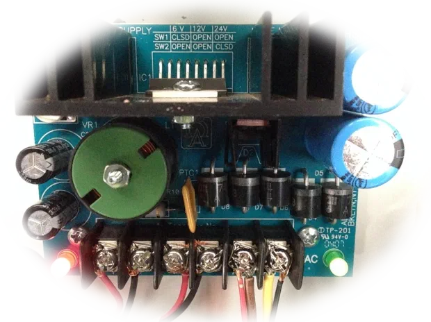
You can think of it as a closed loop for electrons – electrons can’t flow if the loop isn’t closed.
If the circuit is broken (e.g. a wire is broken or a switch is open), the current stops and the devices don’t work.
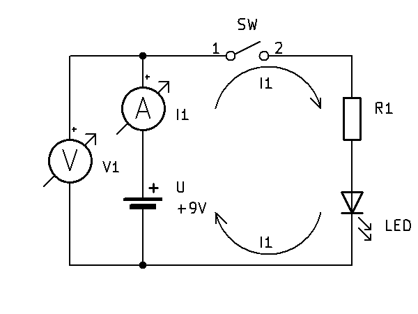
The circuit we will look at below is made up of a power supply U, a switch SW, a resistor R1 and an LED. The circuit also includes measuring instruments, which we use to measure voltage and current:
What is current?
Electric current is actually a flow of electrons through a conductor (e.g. a wire).
Electrons are parts of atoms that have a negative charge.
When you connect a battery or a power supply to a circuit, electrons start to flow from the negative terminal towards the positive terminal.
This flow of electrons is the current.
Conventional current flows from the positive terminal to the negative terminal.
How is current measured?
Current is usually marked with the symbol I.
The unit of current is the ampere (A).
Small hobby circuits (LEDs, micro:bit) usually use currents that we measure in milliamperes (mA), i.e. thousandths of an ampere.
The measuring instrument that measures current is called an ammeter.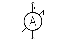
To measure the current through a conductor correctly, the ammeter has to become part of the circuit, i.e. we break the circuit and connect it again through the ammeter (see the schematic above).
The internal resistance of an ammeter is negligible for most of our needs, so we assume that it doesn’t affect the behaviour of the circuit.
How does current work in a circuit?
Current carries energy to devices (an LED, a motor, a speaker).
If the current flows too fast or too many electrons pass through, the device can break, which is why we use resistors to control how much current goes through the device.
What is voltage?
Voltage is the potential difference between two points that drives electrons to flow through the circuit.
The higher the voltage, the harder it pushes electrons through the circuit (with the same resistance, the current is higher).
How is voltage measured?
Voltage is usually marked with the symbol U or V. The unit of voltage is the volt (V). In electronics we will mostly work with voltages up to 9 V (less often up to 12 V), which are not dangerous to people.
The measuring instrument that measures voltage is called a voltmeter.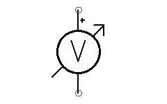
A voltmeter is connected to the two points in the circuit between which we want to measure the voltage (see the schematic above).
The internal resistance of a voltmeter is very high, so the current flowing through it is negligible for most of our needs, and we assume that it doesn’t affect the behaviour of the circuit.
What is resistance?
Resistance (resistor) is a limiting element (load) for the current in a circuit.
It limits how many electrons can flow through a wire or a device.
Without a resistor, electrons could flow too fast and destroy the LED or the motor.
How is resistance measured?
Resistance is usually marked with the symbol R.
The unit is the ohm (Ω).
Resistors have stripes in different colours that show their value (e.g. 220 Ω, 1 kΩ).
You will often see versions where the letter E is used instead of the unit Ω, or where the multiplier prefix is put in place of the decimal point (e.g. 2k2 = 2.2 kΩ, 1M5 = 1.5 MΩ).
The measuring instrument that measures resistance is called an ohmmeter.
We connect it to the two points between which the component or circuit whose resistance we want to measure is connected.
Because the ohmmeter passes a small current through the component to measure its resistance, for an accurate measurement it is best to take the component out of the circuit.
The ohmmeter can affect how the circuit works because of the current it passes through it.