
Review of electronics basics and measurement
Connect, measure, check: electronics basics through real components and hands-on experiments
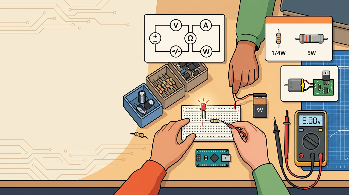
In this workshop we will review the most important electronics basics through short questions, real components and hands-on measurements. We won’t just learn definitions: we will build a simple electric circuit, measure a battery and resistors, and learn how a multimeter becomes a tool for checking your own circuit.
The goal is that after the workshop we can recognise basic electronic components, explain what they do, and safely measure voltage, resistance and current. This is important preparation for future Arduino projects, sensors, automation and building our own electronic devices.
We work like engineers
A good electronics engineer doesn't connect parts at random and doesn't guess when something doesn't work. First they look at the schematic, then they check the connections and find the problem by measuring.What will we review?
Electronic circuits can look very different: from a single LED to an Arduino device with sensors, a display, a motor and a program. Yet many of them are based on the same basic concepts.
In this workshop we will review:
- What a closed circuit is.
- What voltage, current, resistance and power are.
- How a battery, wires, a resistor, an LED, a push button and a capacitor work.
- How to recognise components by their symbol, shape, markings and legs.
- How to use a universal measuring instrument, or multimeter, safely.
- How to measure voltage, resistance and current.
- How to roughly calculate the power of a simple circuit.
- Why some components can be connected either way round, while others have polarity.
- Why an Arduino pin isn’t used as a power source for every device.
A simple electric circuit
For an electronic device to work, it needs a closed path through which current can flow.
In the simplest example we use:
- A power source – a battery or another low-voltage power supply.
- Conductors – wires that connect the parts.
- A load – a component that converts energy into light, sound, heat or movement.
- Control – a push button, switch, transistor or Arduino that decides when the circuit will work.
A simple LED circuit can look like this:
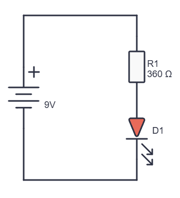
The battery provides the energy, the wires create the path, the resistor limits the current, and the LED converts part of the energy into light.
If the path is broken, the LED won’t light up. If we turn the LED the wrong way round, it usually won’t light up either. If we connect it without a resistor, too much current can flow through it and the LED can be damaged.
Voltage, current, resistance and power
To work with electronics, we need to know four basic quantities.
| Quantity | Symbol | Unit | What it tells us |
|---|---|---|---|
| Voltage | U | volt [V] | How big the difference in electric potential between two points is |
| Current | I | ampere [A] | How much electric charge flows through the circuit |
| Resistance | R | ohm [Ω] | How much a component limits the flow of current |
| Power | P | watt [W] | How quickly electrical energy is converted into light, heat, sound or movement |
For simple direct current (DC) circuits we use Ohm’s law:
From it we can also calculate the current:
Power is calculated with this formula:
This means that a higher voltage or a higher current usually means more power. Part of that power can become light in an LED, sound in a buzzer, movement in a motor or heat in a resistor.
Important: more power means more heat
A component that uses or conducts more energy can get hot. That is why higher-power resistors are often physically bigger, and more powerful transistors, MOSFETs and regulators often have a metal tab or a heatsink.The multimeter
A universal measuring instrument, often called a multimeter, is used to measure electrical quantities. In this workshop we will use it to measure:
- The DC voltage of a battery.
- The resistance of a resistor.
- The continuity of a wire or a connection.
- The current through a simple LED circuit.
- The approximate power, using the measured voltage and current.
Before measuring, we always check:
- That the probes are undamaged.
- That the black probe is in the COM socket.
- That the red probe is in the correct socket.
- That the instrument’s dial is set to the correct function.
- Whether we are measuring voltage, resistance or current.
- Whether the power should be on or off, depending on the type of measurement.
| What do we measure? | Black probe | Red probe | Marking on the instrument | How do we connect the instrument? |
|---|---|---|---|---|
| Voltage | COM | VΩ | V⎓ | In parallel, across the source or component |
| Resistance | COM | VΩ | Ω | Across the component, with no power |
| Continuity | COM | VΩ | speaker or diode symbol | Across the wire or connection, with no power |
| Current | COM | mA or 10A | A⎓ or mA⎓ | In series, as part of the circuit |
Measuring voltage
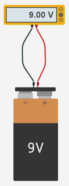
Voltage is measured in parallel. This means that we touch the probes to the two points between which we want to find the voltage difference.
To measure a 9 V battery:
- We plug the black probe into COM.
- We plug the red probe into VΩ.
- We set the instrument to DC voltage, V⎓.
- If the instrument doesn’t have auto-ranging, we choose a range higher than 9 V, for example 20 V.
- We touch the black probe to the minus of the battery.
- We touch the red probe to the plus of the battery.
- We read the measured value.
A battery marked 9 V doesn’t have to show exactly 9.00 V. A new battery may show a little more, and a used one less. Also, a battery with no load may show a good voltage, but its voltage can drop considerably when it tries to power a motor or another device that draws more current.
Measuring voltage:
Measuring resistance
Resistance is measured only when the circuit has no power. It is best to measure a resistor that isn’t connected in a working circuit.
To measure a resistor:
- We switch off and disconnect the power.
- We plug the black probe into COM.
- We plug the red probe into VΩ.
- We set the instrument to Ω.
- We touch one probe to one leg of the resistor and the other probe to the other leg.
- We read the value and compare it with the colour bands on the resistor.
Resistors have a tolerance, so the measured value doesn’t have to be exactly the same as the nominal value. For example, a resistor marked 1 kΩ may measure a little less or a little more than 1000 Ω.
We don't measure resistance on a powered circuit
Before measuring resistance, we must switch off the power. If the resistor is connected in parallel with other parts, the instrument may show the wrong value, because it measures the whole path between the probes, not just the resistor we want to check.Instructions for digital multimeters specifically say that the circuit’s power should be disconnected before measuring resistance, continuity, diodes or capacitance.
Measuring current
Current isn’t measured the same way as voltage.
When measuring voltage, the multimeter looks at two points in the circuit. When measuring current, the multimeter has to become part of the path the current flows through. That is why current is measured in series.
Measuring the current through an LED circuit:
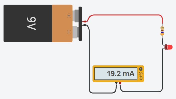
To measure the current through an LED circuit:
- We switch off the power.
- We break one part of the circuit’s series path.
- We plug the black probe into COM.
- We plug the red probe into the mA or 10A socket, depending on the expected current and the instrument’s markings.
- We set the instrument to DC current, A⎓ or mA⎓.
- We use the probes to bridge the gap we made in the circuit.
- We switch on the power and read the current.
- We switch off the power.
- After measuring, we put the red probe back in the VΩ socket.
The most important rule for measuring current
We never connect a multimeter set to measure current directly between the plus and minus of a battery. This can create a short circuit, drain the battery or blow the fuse in the instrument.When measuring current, the instrument is connected in series, and the power is switched off before the instrument is connected into the circuit.
Measuring power
Most multimeters don’t measure power directly. For a simple DC circuit, we can calculate the power from the measured voltage and current:
If the battery voltage is about 9 V and the measured current through the LED circuit is about 20 mA (0.020 A), the total power of the circuit is:
The power in a circuit is shared between the components. The resistor turns part of the energy into heat, and the LED turns part of the energy into light and heat. That is why, when designing a circuit, we look not only at the resistance value but also at the resistor’s power rating.
Components we use
In Arduino projects we use various components. Some are used for input, some for output, and some protect or control larger loads.
| Component | How to recognise it? | What is it for? | Does it have polarity? |
|---|---|---|---|
| Resistor | Small cylinder with coloured bands | Limits current and divides voltage | No |
| LED | Clear or coloured body, two legs | Light indicator or effect | Yes |
| Ordinary diode | Small cylindrical or glass body with a band | Lets current through mainly in one direction | Yes |
| Electrolytic capacitor | Cylindrical body marked with capacitance and voltage | Stores energy and stabilises the power supply | Yes |
| Ceramic capacitor | Small disc or rectangular component | Filters out interference and stabilises the circuit | Usually not |
| Push button | Small mechanical switch | Digital input: pressed or not pressed | No |
| Potentiometer | Rotary knob with three terminals | Variable analogue input | No |
| Photoresistor (LDR) | Round disc with a visible wavy track | Changes its resistance with the amount of light | No |
| Transistor | Small body with three legs | Electronic switch or amplifier | Yes |
| MOSFET | Three legs, often a bigger body or a module | Controls more powerful DC loads | Yes |
| Buzzer | Small cylinder, often marked with a + sign | Makes sound | Often yes |
| Servo motor | Case with a shaft and three wires | Moves to a set position | Yes |
| DC motor | Two wires and a shaft | Produces continuous rotation | Direction depends on polarity |
You can see the symbols for these components here: Electronic components, symbols and diagrams.
Resistors and power
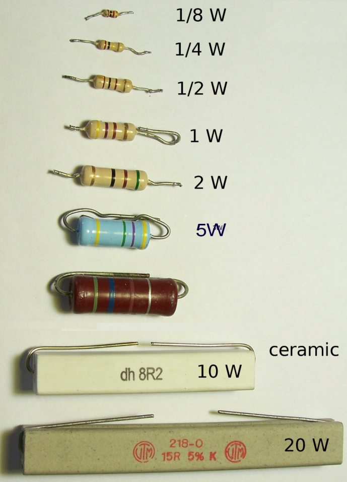
A 1/4 W resistor is often enough for LEDs and simple Arduino circuits. Resistors that can handle more power are usually bigger, because they have to give off more heat to their surroundings safely.
LEDs and polarity
An LED is a diode, which means it has to be connected the right way round.
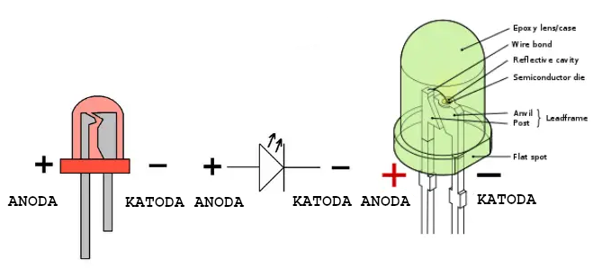
The longer leg is usually the anode and goes towards the more positive voltage.
The shorter leg is usually the cathode and goes towards minus.
The flat side of the LED’s body usually marks the cathode.
An LED always needs a resistor or another suitable current-limiting circuit.
Electrolytic capacitors
An electrolytic capacitor has polarity. On its body, a stripe with minus symbols usually marks the negative side, and on versions with straight legs the shorter leg is usually the negative one.
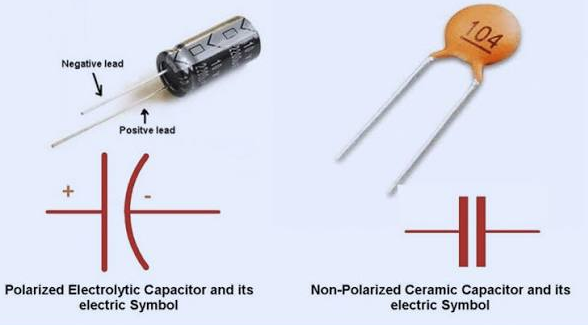
- The capacitance, for example 100 µF.
- The maximum allowed voltage, for example 16 V.
A capacitor marked 100 µF 16 V can be used in a circuit up to 16 V, but we must not connect it to a higher voltage. We also must not connect it with reversed polarity.
Arduino: inputs and outputs
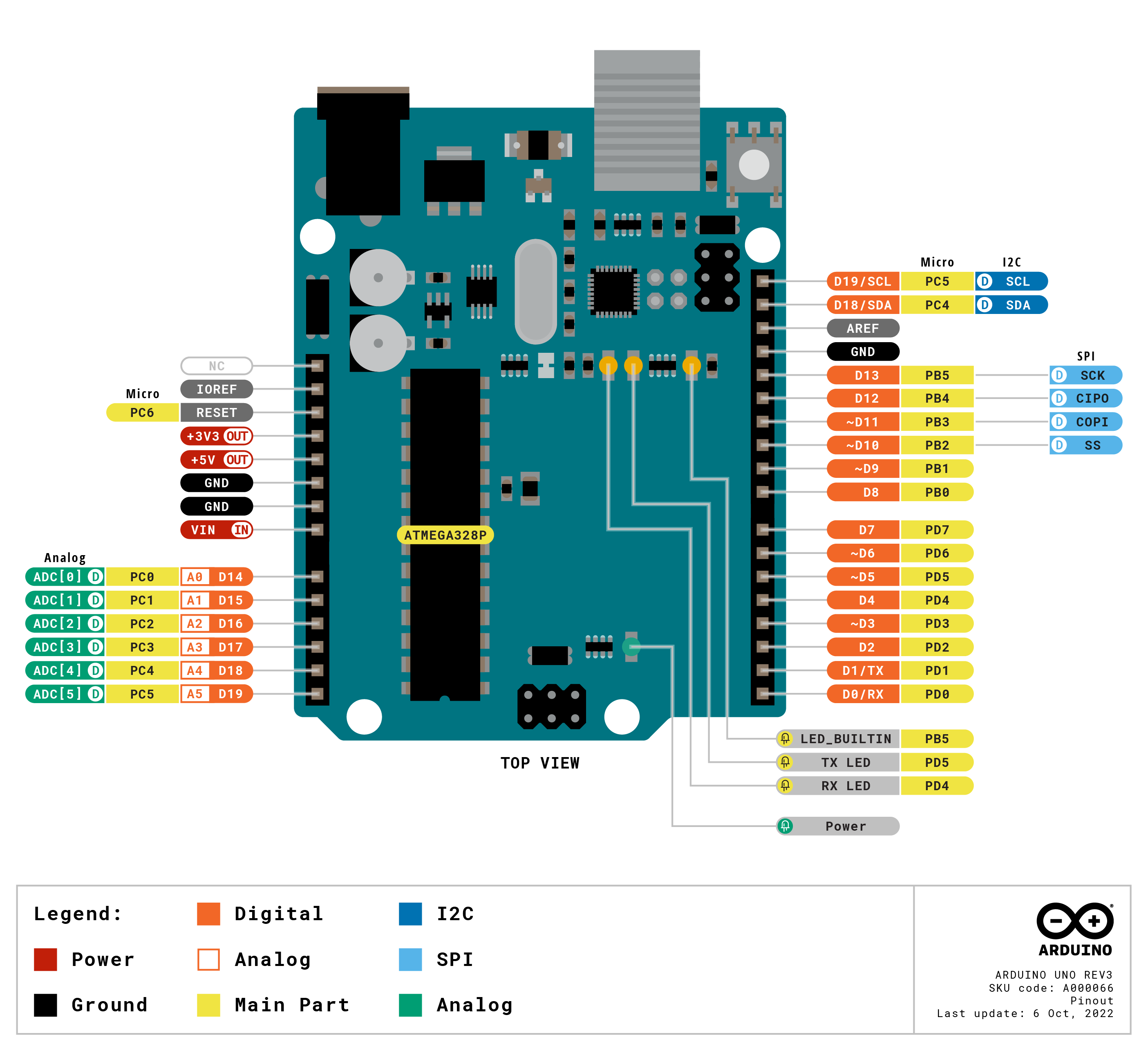
The Arduino is a microcontroller: a small board that can read information from its surroundings and control electronic devices.
- Push button
- Potentiometer
- Photoresistor (LDR)
- Temperature sensor
- Distance sensor
- Switch
Components that the Arduino sends commands to are called outputs:
- LED
- Buzzer
- Display
- Servo motor
- Motor driver
- Lighting effect
- Relay or MOSFET module for a low-voltage load
Arduino pins can be set as inputs or outputs. An analogue input can read a changing voltage level, for example the signal from a potentiometer or a light sensor, while a digital input usually recognises two states: HIGH and LOW.
An Arduino pin isn't a power supply for everything
We can control an LED with an Arduino pin if we use a correctly chosen resistor. A motor, servo, relay, electromagnet or a more powerful LED strip often needs more current than an Arduino pin can safely supply. For devices like these we use a suitable transistor, MOSFET, motor driver or a separate power supply.A little quiz
1. Which four basic parts must a simple electric circuit have for an LED to light up safely?
2. What is voltage and what unit is it measured in?
3. What is current and what unit is it measured in?
4. What does a resistor do?
5. What unit is resistance measured in?
6. How is a multimeter connected when we measure the voltage of a battery?
7. Can we measure resistance on a circuit that is connected to a battery or USB power?
8. How is a multimeter connected when we measure the current through an LED?
9. What can happen if we connect a multimeter set to measure current directly between the plus and minus of a battery?
10. How do we calculate electrical power in a simple DC circuit?
11. Why is a 5 W resistor usually physically bigger than a 1/4 W resistor?
12. How can we recognise the polarity of an LED?
13. How do we recognise the polarity of an electrolytic capacitor?
14. Why don't we connect a motor or a servo directly to an Arduino digital pin?
15. What is the difference between a push button and a potentiometer as an Arduino input?
16. What do you do if a component, battery or wire gets hot, smokes or smells of burning?
 What did we learn?
- Today we reviewed that an electronic circuit isn’t just a collection of wires and components. For it to work safely and predictably, we need to know where the energy comes from, which path it takes and what each component does.
- We learned that a simple electric circuit needs a power source, conductors, a load and a closed path back to the source. In an LED circuit, the resistor isn’t an unimportant extra: it limits the current and protects the LED.
- We reviewed the four basic electrical quantities:
- Voltage U is measured in volts [𝑉] and describes the difference in electric potential between two points.
- Current I is measured in amperes [𝐴], often in milliamperes [𝑚𝐴], and tells us how much electric charge flows through part of the circuit.
- Resistance R is measured in ohms [Ω] and limits the flow of current.
- Power P is measured in watts [𝑊] and tells us how quickly electrical energy is converted into light, sound, heat or movement.
- We used the formulas of Ohm’s law and the formula for calculating power.
- We also learned how to use a multimeter correctly to measure:
- voltage: in parallel, between two points
- resistance: across the component; the power must be off
- continuity: across a wire or connection; the power must be off
- current: in series, as part of the circuit
- Measuring current has a special rule: we switch off the power, break the circuit, insert the multimeter into the gap, and only then switch the power on. After measuring, we put the red probe back in the VΩ socket. Official safety instructions for multimeters also stress that current is measured in series and that resistance is not measured on a live circuit.
- We also got to know the basic components we will use in Arduino projects:
- A resistor limits current.
- An LED converts electrical energy into light and has polarity.
- A push button and a switch give digital information: pressed or not pressed.
- A potentiometer and a photoresistor can give a changing, analogue value.
- An electrolytic capacitor stores energy and must be connected with the correct polarity.
- A diode lets current through mainly in one direction.
- A transistor and a MOSFET let a small signal control a larger load.
- A buzzer makes sound.
- A servo and a DC motor convert electrical energy into movement.
- We also saw that the physical appearance of a component often tells us something about its limits. Components that can handle more power are often bigger, have thicker legs, a metal tab or a heatsink, or sit on a separate module.
- With the Arduino, we distinguish between inputs and outputs:
- Inputs send information to the Arduino: a push button, potentiometer, photoresistor or sensor.
- Outputs carry out the Arduino’s commands: an LED, buzzer, display, servo or motor driver module.
- The Arduino’s analogue inputs can read changing voltage values, while the digital pins can be set as inputs or outputs.
The most important message of the workshop
We don't connect things at random. First we look at the schematic, then we check the power supply, polarity and connections, and then we measure. When something doesn't work, we change one thing at a time.In the next workshops we will build on these basics: the Arduino will read push buttons and sensors, and then control LEDs, sound, displays and other parts of our projects.