
Voltage divider, Arduino and PWM
From measuring the voltage on a potentiometer to an LED that warns when a threshold is crossed
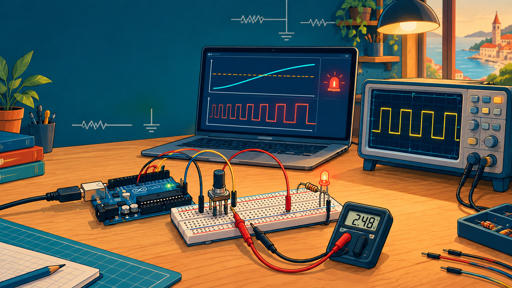
In the last workshop we saw how a change in resistance can affect an electronic circuit. Today we will explore that idea step by step: first we will use a potentiometer to make an adjustable voltage divider and measure its output, and then we will connect that output to an Arduino Uno. The program will read the voltage, control the brightness of an LED and finally turn it into a warning signal.
The potentiometer as a voltage divider
A voltage divider is made of two resistances connected one after the other between the power supply and ground. We measure the voltage at the point between them.
A variable resistor (potentiometer) behaves like two resistors connected as a voltage divider, except that their values are changed mechanically (e.g. by turning the potentiometer’s shaft).
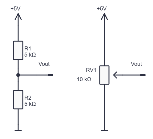
If we know both resistances, we can calculate the output voltage:
The current flowing through an unloaded voltage divider is:
The same current flows through both series-connected parts, so we can also calculate the voltages across them as
Their sum is equal to the input voltage. These formulas assume that no load drawing a significant current is connected to the divider’s output; a divider is for creating a measurement signal, not for powering a bigger device.
Exercise 1: Measure the voltage
On the breadboard we connect a 10 kΩ potentiometer:
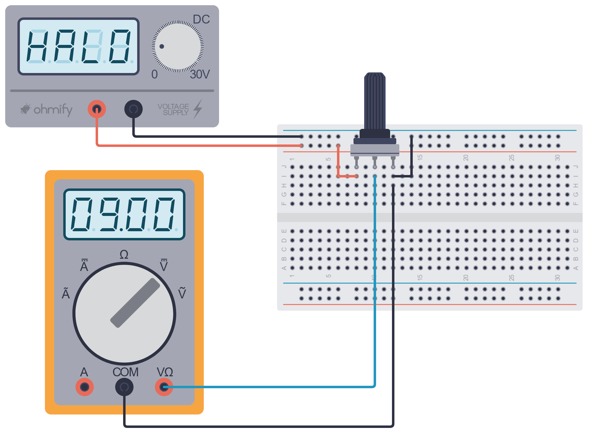
Unlike in the last exercise, here we don’t connect the middle terminal to an end terminal. Now we use all three terminals: the two end terminals span the whole resistive track, and the middle one is the divider’s moving output. By turning the shaft we change how much of the resistance is above the wiper and how much is below it.
Before switching on, we check where the probes are plugged in: the red one must be in the socket for measuring voltage, usually VΩ, not in mA or A. We set the meter to DC voltage (V=) and measure in parallel, between the wiper and GND.
What do we expect?
- wiper close to the end connected to GND: about 0 V
- wiper in the middle: about 2.5 V
- wiper close to the end connected to +5 V: about 5 V
If the total resistance of the potentiometer is 10 kΩ and the supply is 5 V, roughly 5 V / 10000 Ω = 0.5 mA flows through its resistive track. Halfway along the track we have roughly 5 kΩ above and 5 kΩ below the wiper, so we expect about 2.5 V. The actual reading can differ slightly because of the wiper position and the actual source voltage.
Things to observe:
- Turn the potentiometer slowly. Does the voltage change gradually?
- Can you set it to about 1 V, 2.5 V and 4 V?
Exercise 2. The Arduino reads the divider
The voltmeter is still useful for checking, but now we also connect the potentiometer’s wiper to analogue input A0 of the Arduino Uno. The end terminals stay on +5V and GND; all parts must use a common GND.
We connect the LED to PWM pin D9 through a 470 Ω series resistor. A pin of the Arduino UNO R4 board can supply about 8 mA at most, and with 470 Ω about 6 mA flows through the LED:
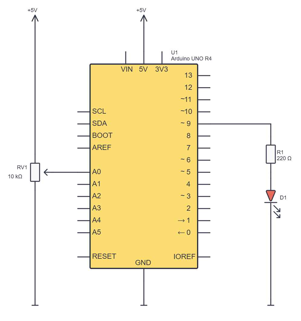
The Arduino Uno reads the voltage at A0 and converts it into a whole number from 0 to 1023. Roughly: 0 V gives 0, 2.5 V gives a value around the middle of the range, and 5 V gives a value close to 1023. analogRead() doesn’t return volts; it returns a number that represents the measured voltage.
// C++
const int potPin = A0;
const int ledPin = 9;

void setup() {
  pinMode(ledPin, OUTPUT);
  Serial.begin(9600);
}

void loop() {
  int potValue = analogRead(potPin);
  int ledBrightness = map(potValue, 0, 1023, 0, 255);

  analogWrite(ledPin, ledBrightness);

  Serial.print(potValue);
  Serial.print(", ");
  Serial.println(ledBrightness);

  delay(50);
}
How do we read the program?
setup()andloop()are the foundation of every Arduino program’s structure: the first prepares the device, and the second repeats actions.const int potPin = A0;– We have given the input pin a name.constmeans that this name doesn’t change while the program runs.const int ledPin = 9;– We have named the output pin for the LED.void setup()– The part of the program that runs once after starting or resetting.pinMode(ledPin, OUTPUT);– Sets D9 as an output.Serial.begin(9600);– Starts serial communication with the computer at 9600 baud.void loop()– The part of the program that keeps repeating while the Arduino is running.int potValue = analogRead(potPin);– Reads the analogue input and stores the result in a variable.map(...)– Converts a value from one number range to another.analogWrite(...)– Sets the PWM value on D9.Serial.print(...)– Prints a value and carries on writing on the same line.Serial.println(...)– Prints a value and ends the line (moves on to a new line).delay(50);– Waits 50 milliseconds before the next pass throughloop().
Why map()? The input and the output don’t have the same number of possible values: the A0 reading goes from 0 to 1023, while the value we send to analogWrite() in this exercise goes from 0 to 255. This way, for example, an input around the middle of its range becomes an output around the middle of the PWM range.
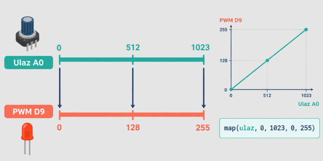
Text and graph
The Arduino sends data to the computer over the USB connection using serial communication. In the Serial Monitor we see lines of numbers. In the Serial Plotter the same numbers can be shown as lines on a graph. We print a comma between the values, and Serial.println() ends the line so that the Plotter knows where the next sample begins. The Arduino documentation shows exactly this kind of output of several values, including a constant reference line.
Turn the potentiometer and compare:
- The voltage shown by the voltmeter.
- The
potValuenumber shown by the Serial Monitor. - The value of
ledBrightness. - The visible brightness of the LED.
The number 255 doesn’t mean 255 volts. It is the program value we use to set the maximum PWM output in this example.
What is on pin D9?
Now we use the voltmeter to measure the wiper voltage relative to GND, while the workshop leader uses an oscilloscope to look at D9 relative to GND. We connect the oscilloscope probe only to our low-voltage circuit; its ground clip goes to GND.
At A0 we have a fairly steady, adjustable voltage between 0 and 5 V. At D9 we don’t have a smooth analogue voltage that changes gradually from 0 to 5 V. Instead, the Arduino Uno sends a PWM signal there: a series of fast switches between roughly 0 V and 5 V. The value from 0 to 255 sets what fraction of the time the signal is on.
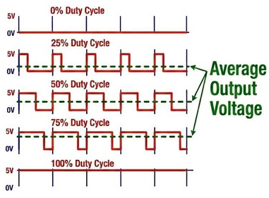
- 0 → 0% → the LED is off
- 64 → 25% → the LED looks dimmer
- 128 → 50% → the LED looks brighter
- 255 → 100% → the LED is fully on
So on the oscilloscope we will see that the width of the “on” part of the pulse changes, not the height of the pulse voltage. On Arduino Uno pin D9 the PWM frequency with the default settings is about 490 Hz. The LED switches on and off so quickly that we usually notice only a change in its apparent brightness. The relationship between the PWM value we set and what looks “twice as bright” to the eye is not completely linear.
A voltmeter on D9 may show some average value, depending on the meter. The oscilloscope reveals what that reading hides: the signal is actually switching between two levels all the time.
Exercise 3. Can the Arduino be an oscilloscope?
Not in this simple form. As an extra experiment, we can use a wire to connect D9 to a free analogue input, A1, and read that pin. We don’t disconnect the potentiometer’s wiper from A0 while doing this: A0 stays the input for the divider, and A1 becomes the input for watching the PWM signal.
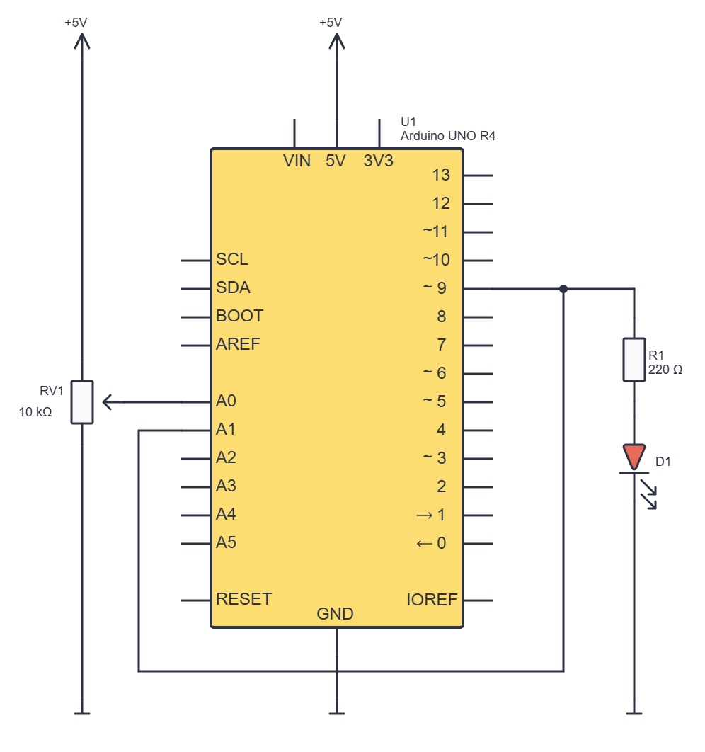
We don’t add a second power supply to A1. D9 and A1 are pins of the same Arduino Uno, so they already share ground. We connect the wire with the USB unplugged and switch the circuit on only after checking it. D9 may be connected to A1 only while A1 is an analogue input; in another program we must not set it up as an output driven against D9.
// C++
const int potPin = A0;
const int ledPin = 9;
const int monPin = A1;

void setup() {
  pinMode(ledPin, OUTPUT);
  Serial.begin(9600);
}

void loop() {
  int potValue = analogRead(potPin);
  int ledBrightness = map(potValue, 0, 1023, 0, 255);

  analogWrite(ledPin, ledBrightness);

  int signal = analogRead(monPin);

  Serial.print(potValue);
  Serial.print(", ");
  Serial.print(ledBrightness);
  Serial.print(", ");
  Serial.println(signal);

  delay(50);
}
This is an important experiment precisely because the result can be surprising. A1 takes an instantaneous sample of the PWM signal: it may catch roughly 0 V or roughly 5 V, so the reading is often close to 0 or 1023. Successive samples won’t necessarily draw a neat curve of the pulse width. The Serial Plotter draws the samples sent to the computer; it doesn’t show the waveform the way an oscilloscope does. To really look at the pulses, we use an oscilloscope.
Exercise 4. When the value crosses a threshold
Now we add a new rule to the program:
- when the reading on A0 crosses a set threshold, the LED will blink.
This can stand for a warning when a critical value is reached.
A threshold of 800 is not exactly 80% of 1023: exactly 80% is about 818. To start with, we will still use 800 as an easy-to-read, rounded threshold – about 78% of the range. If you want the threshold closer to 80%, replace 800 with 818.
// C++
const int potPin = A0;
const int ledPin = 9;
const int monPin = A1;
const int threshold = 800;

bool ledMode = true;
int count = 10;

void setup() {
  pinMode(ledPin, OUTPUT);
  Serial.begin(9600);
}

void loop() {
  int potValue = analogRead(potPin);
  int ledBrightness = map(potValue, 0, 1023, 0, 255);

  if (potValue > threshold) {
    if (!ledMode) {
      ledBrightness = 0;
    }

    count--;

    if (count == 0) {
      count = 10;
      ledMode = !ledMode;
    }
  }

  analogWrite(ledPin, ledBrightness);
  int signal = analogRead(monPin);

  Serial.print("Threshold:");
  Serial.print(threshold);
  Serial.print(", Input:");
  Serial.print(potValue);
  Serial.print(", PWM:");
  Serial.print(ledBrightness);
  Serial.print(", A1:");
  Serial.println(signal);

  delay(50);
}
What is new in the program?
const int threshold = 800;– The threshold above which we trigger the warning.bool ledMode = true;– Remembers whether the current blinking phase is on or off.int count = 10;– Counts the passes throughloop()before the phase changes.if (potValue > threshold)– Runs the special rules only when the input crosses the threshold.if (!ledMode)– The!sign means not: if the phase is off, the PWM becomes 0.count--;– Decreases the counter by one.if (count == 0)– Checks whether the counter has reached zero; == compares, while = assigns a value.ledMode = !ledMode;– Changes the state from true to false or the other way round.
With delay(50), ten passes through the loop take roughly half a second, but not exactly: reading the inputs and printing to serial also take time. So the LED spends roughly half a second in one phase and half a second in the other. The code deliberately keeps the last phase and the counter value when the potentiometer goes back below the threshold. This means that when the value crosses 800 again, the warning may continue from the middle of the previous cycle. For the workshop this is an interesting example of state that the program remembers, but for a predictable device we would reset ledMode = true and count = 10 when leaving the warning.
Why do we print the line Threshold: 800?
It is important to read the graph’s axes: Input and A1 are readings from roughly 0 to 1023, while PWM is a set value from 0 to 255. All the curves can share the same axis, but they don’t represent the same physical quantities.
A threshold isn't always a clean boundary
If the reading hovers around 800 and wobbles a little, the LED can jump in and out of warning mode erratically. In a real device we would add two limits, for example switching the warning on above 820 and switching it off only below 780. This is called hysteresis.
Extra task: adjusting the speed
Build another voltage divider with a second 10 kΩ potentiometer and connect it to analogue pin A2.
The first potentiometer on A0 decides when we cross the threshold. The second potentiometer on A2 decides how fast the LED blinks.
We want to turn the A2 reading from 0 to 1023 into a number of counter steps from 0 to 50. But there is a trap: if we set count to 0 and the next statement is count--, the counter becomes −1 and the condition count == 0 will never be met again. So we may calculate the range 0–50, but for the actual counter we must choose at least 1.
We don’t try to use analogRead(A2) as the initial value of a global variable before setup(); the Arduino first has to start up its hardware. We initialise the counter after start-up and read it again every time it reaches zero.
We keep the program from the previous exercise and change only this: below the existing constants add speedPin, replace the line int count = 10; with int count = 1;, add the function readStepCount() before setup(), and add count = readStepCount(); at the end of setup():
// C++
// potPin, ledPin, monPin, threshold and ledMode stay as in the previous program.
const int speedPin = A2;
int count = 1;

int readStepCount() {
  int speedReading = analogRead(speedPin);
  int steps = map(speedReading, 0, 1023, 0, 50);
  return max(1, steps);
}

void setup() {
  pinMode(ledPin, OUTPUT);
  Serial.begin(9600);
  count = readStepCount();
}
And inside the existing condition, replace:
// C++
if (count == 0) {
  count = readStepCount();
  ledMode = !ledMode;
}
The readStepCount() function is our own function: it groups several statements that have one job and returns a result. max(1, steps) stops the number of steps from being 0. The larger the number of steps, the longer we wait for the phase to change – the LED blinks more slowly. At very small values the blinking can be hard to see clearly; delay(50) and the serial output also affect the actual timing. For precise timing we will later use millis().
Where would this be useful?
We can apply the same basic pattern to a warning when some measured quantity crosses a set limit:
sensor ⇒ analogue input ⇒ comparison with a threshold ⇒ blinking LED
Today the potentiometer plays the part of a sensor whose value we can easily control. In a future project we could use a suitably connected water level, temperature or light sensor instead. Before using it for real, we would need to check how that sensor creates its signal, what its threshold means and what the device must do when the sensor or a wire fails.
Questions to think about
How could we show the set PWM value from 0 to 255 as a percentage from 0% to 100%? How could that number be shown to the user?
int percent = map(ledBrightness, 0, 255, 0, 100);To display it, we could use an OLED or LCD screen, a seven-segment display or a row of LEDs as a simple indicator. Keep in mind that the percentage tells us what PWM share we set, not that we measured the LED’s actual brightness. To measure brightness we would need a suitable light sensor.
 What did we learn?
- A potentiometer with its end terminals on +5 V and GND and its output on the middle terminal works as an adjustable voltage divider.
- We calculate the divider voltage from the ratio of the two resistances, and the current through an unloaded divider from their total resistance.
- The voltmeter measures the voltage between the wiper and GND; Arduino A0 turns the same signal into a number from 0 to 1023.
setup()prepares the pins and serial communication, andloop()keeps repeating the reading, processing and output control.intholds whole numbers,boola logical state, andconstmarks a value we don’t change in the program.- The Serial Monitor shows the lines that are sent, and the Serial Plotter draws a graph from them.
analogWrite()on D9 doesn’t give a smooth analogue voltage: it sends a PWM signal between roughly 0 V and 5 V.- The oscilloscope shows the shape of the PWM pulses; simply reading D9 on A1 only gives individual samples and doesn’t replace an oscilloscope.
- An if condition, a logical variable and a counter let the LED change its behaviour when the reading crosses a threshold.
- A constant threshold line on the graph helps us see when the warning condition is met.
A little quiz
1. How do we connect the three terminals of a potentiometer when we use it as a voltage divider?
2. Roughly what voltage do we expect on the wiper if it is exactly in the middle of a potentiometer connected between 5 V and GND?
3. What is the formula for the output voltage of a divider with two series resistors?
4. Does analogRead(A0) measure voltage in volts?
5. What is the difference between setup() and loop()?
6. Why do we use map(potValue, 0, 1023, 0, 255)?
7. What does the oscilloscope show on D9 when analogWrite(9, 128) is used?
8. Why is reading pin A1 connected to D9 not the same as an oscilloscope view of the PWM?
9. What does the condition if (potValue > threshold) mean?
potValue is greater than the set limit threshold.