
Diagrams
Block diagrams and schematics
Introduction
When we build an electronics project, we don’t always draw the same kind of drawing, because each one has a different purpose. A functional or block diagram helps us quickly understand what a system does, while a circuit schematic shows how exactly all the parts and pins are connected.
Using the SoundLab project as an example, we can show students that the whole device can first be explained as a few large building blocks: buttons, potentiometers, Arduino, audio output, and an amplifier with a speaker. Only after that does it make sense to move on to the detailed wiring schematic.
Functional and block diagrams
A functional or block diagram works at a higher level of abstraction and shows how information flows between the parts of a system, without showing every wire, resistor and pin. That makes it excellent for a first explanation of how a device works, especially when we want students to understand the idea of the project first.
A circuit schematic is a more precise document: it shows the actual components and their electrical connections, so that someone else can build the same circuit without any further explanation. In other words, a block diagram explains the function, while a schematic makes it possible to actually build the circuit and check the connections.
Role in the project
In the early stage of a project the block diagram is the most useful, because it helps with planning: what inputs we have, what processes the signal and what comes out at the end. For SoundLab this can be a chain: buttons and potentiometers ⇒ Arduino Nano ⇒ sound generation ⇒ volume control ⇒ LM386 amplifier ⇒ speaker.
Later, when the project is actually wired up on a breadboard, perfboard or PCB, we need the circuit schematic, because it defines exactly which pin goes where. That is exactly why teaching often starts with a block diagram and ends with a schematic and the physical wiring.
SoundLab example
In SoundLab, 17 buttons are used as inputs for choosing notes, and 8 potentiometers change the sound parameters, including the ADSR envelope and FM modulation (see the SoundLab project for an explanation of these terms). The Arduino Nano reads these inputs, calculates the sound and sends the audio signal to output pin D9.
These building blocks describe the block diagram well:
- Buttons as input sensors,
- Potentiometers as input sensors,
- Arduino Nano as the centre that processes the input data and forms the output signal,
- A potentiometer for volume control,
- LM386 as the output amplifier,
- A speaker as the output.
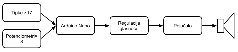
The project states which input pins the buttons are connected to, which pins the potentiometers are connected to, which output pin the amplifier takes its signal from, and so on. To know how to wire all this, we use the circuit schematic:
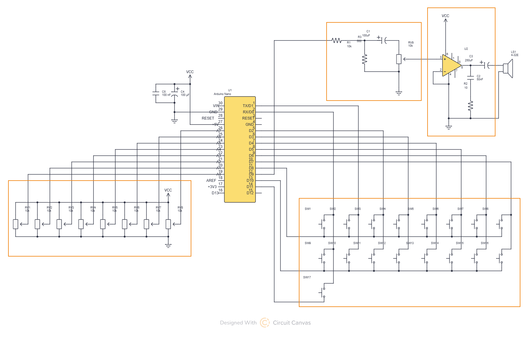
In the boxes we can recognise the parts of our circuit from the block diagram.