SoundLab
Generating sound with Arduino

Introduction
Sound Lab is a project in which we build a small digital-analogue instrument: the Arduino creates the sound, potentiometers control its character, and an LM386 amplifier turns it into a signal strong enough for a speaker. In one project we meet programming, analogue electronics and the basics of audio processing.
In this version of the project we use rotary potentiometers, which let us adjust the sound parameters intuitively by turning knobs, just like on a real audio device. The focus is not only on getting the device to make sounds, but also on understanding why audio circuits need a more careful power supply, tidier grounds and a better component layout than ordinary LED or push button projects.
Project goals
- Explain how the Arduino reads several analogue inputs from potentiometers and turns those values into sound parameters.
- Tell the difference between the small-amplitude signal at the microcontroller output and a signal strong enough to drive a speaker.
- Describe the basic function of the LM386 amplifier, including the input, the output, the power supply, the output capacitor and the optional gain setting.
- Recognise typical audio problems such as noise, hum, distortion and instability caused by a poor power supply or poor wiring layout.
Research and analysis
Task 1: Analysing the functional blocks
- Draw a block diagram of the system:
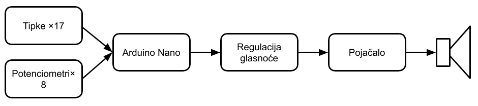
buttons or controls ⇒ Arduino ⇒ audio signal generation on pin D9 ⇒ volume ⇒ LM386 ⇒ speaker.
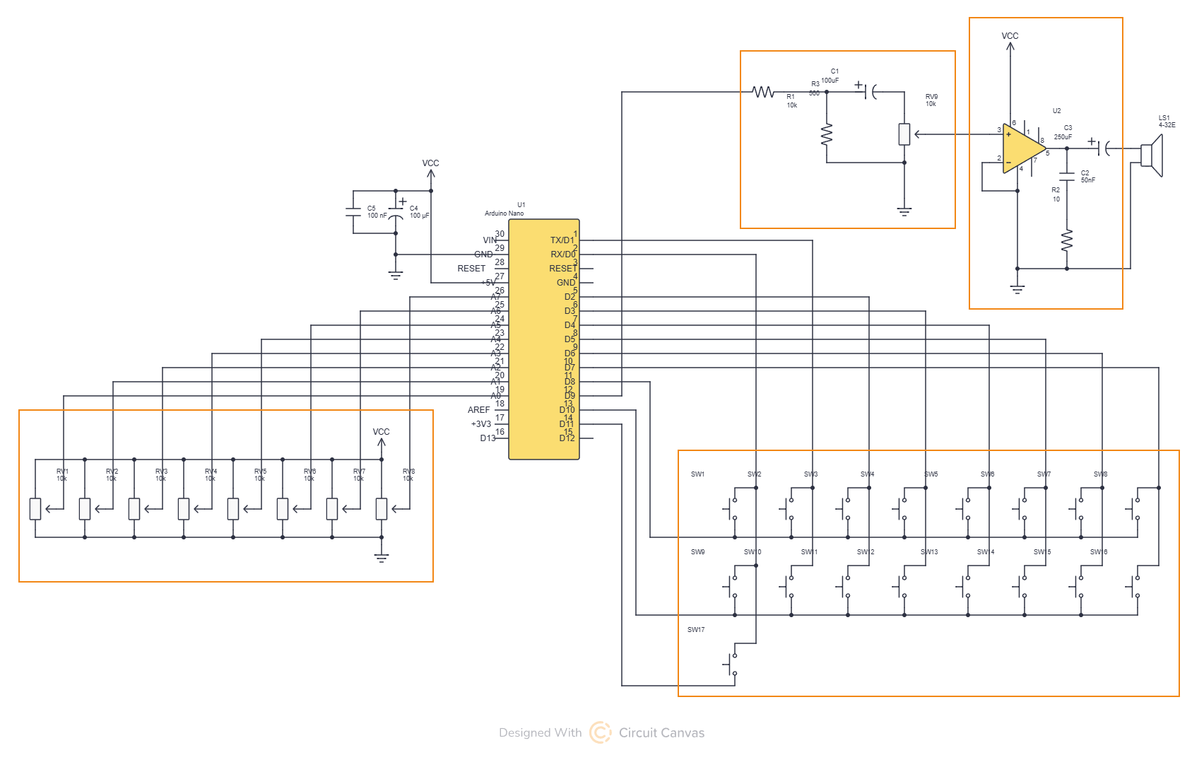
In the original Soundlab project, eight potentiometers are connected to A0–A7, and the audio output comes from D9. - Describe the difference between the control part and the audio part of the circuit.
Task 2: Analysing the rotary potentiometers
- For each potentiometer, label its three terminals: +5 V, GND and the wiper going to the analogue input. The original project uses potentiometers from 1 kOhm to 100 kOhm to control the audio parameters, and an extra 10 kOhm potentiometer is used for the volume.
- Explain what the Arduino actually sees on the middle pin of the potentiometer.
Task 3: Analysing the LM386 amplifier
- Identify the basic pins of the LM386: input, ground, power supply, output and the gain pins.
- Compare two gain configurations: the basic one without a capacitor between pins 1 and 8, and the boosted one with a capacitor that greatly increases the gain.
- Analyse why a high gain is not always a good thing.
Task 4: Analysing the power supply and stability
- Mark which components are there for stability and noise reduction.
- Discuss why an audio circuit is not happy when the digital lines, the speaker power and the analogue inputs run across the breadboard any old way.
- Compare powering the circuit from USB and from an external 5 V supply. The original Soundlab can run from USB or from an external 5 V supply, but how good it sounds depends a lot on how clean and stable the power supply is.
Experiments
Experiment 1: The effect of the volume potentiometer
- Connect a 10 kOhm rotary potentiometer to the LM386 input as a volume control and listen to how the sound level changes. In LM386 projects, a potentiometer like this is typically used exactly there, at the input, for volume.
- Write down your conclusion.
Experiment 2: Gain 20 versus gain 200
- First use the LM386 without a capacitor between pins 1 and 8, then add the capacitor and listen to the output again. This changes the gain from the basic value of 20 to a much higher value, up to 200.
- Write down the differences in loudness, noise, distortion and sensitivity to touching the wires or the breadboard.
- Write down your conclusion.
Experiment 3: The bypass capacitor and noise
- Compare how the circuit works with and without a capacitor on pin 7 of the LM386.
- Listen for any difference in the background noise or dirtiness of the sound when there is no useful signal or when the volume is turned up.
- Write down your conclusion.
Experiment 4: Wiring layout and breadboard noise
- Build two versions of the circuit: a tidy one with short wires and a clear separation between the audio and digital paths, and another that is deliberately sprawled across the breadboard.
- Compare how much hum, crackling or digital noise you can hear in each version.
- Write down your conclusion.
Experiment 5: Potentiometers as sound parameter controls
- Assign each of the rotary potentiometers to one synthesis or sound effect parameter in the program. In the original Soundlab, eight potentiometers control eight sound parameters.
- Write down which potentiometers change the character of the sound the most, and which only subtly change the envelope or texture of the tone.
- Write down your conclusion.
What some of these terms mean:
The ADSR envelope describes how the loudness of a sound changes shape over time.
ADSR stands for Attack, Decay, Sustain, Release – the four phases that the loudness of a note or sound goes through.
- Attack – how quickly the sound rises from silence to its maximum after you press a key.
- Decay – how quickly the loudness drops from that maximum to a lower, steady level.
- Sustain – the loudness level while you keep the key pressed; this is where the sound is sustained.
- Release – how quickly the sound fades away when you let go of the key.
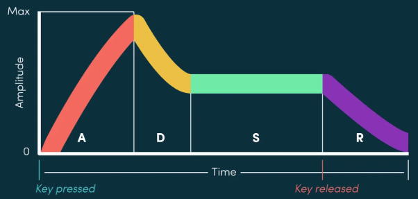
As a graph, the ADSR envelope is a curve that describes how the amplitude (loudness) develops over time – that is why it is called an envelope: it wraps around the actual waveform of the sound. In synthesisers, ADSR is often used to shape the loudness (VCA), but the same idea can be applied to other parameters too, e.g. a filter.
Example:
- short attack and release → the sound of a drum, a click
- longer attack and release → the sound of strings slowly swelling and fading
FM modulation describes how we change the frequency of a signal using another signal.
FM means frequency modulation: we carry information by changing the frequency of a basic carrier signal.
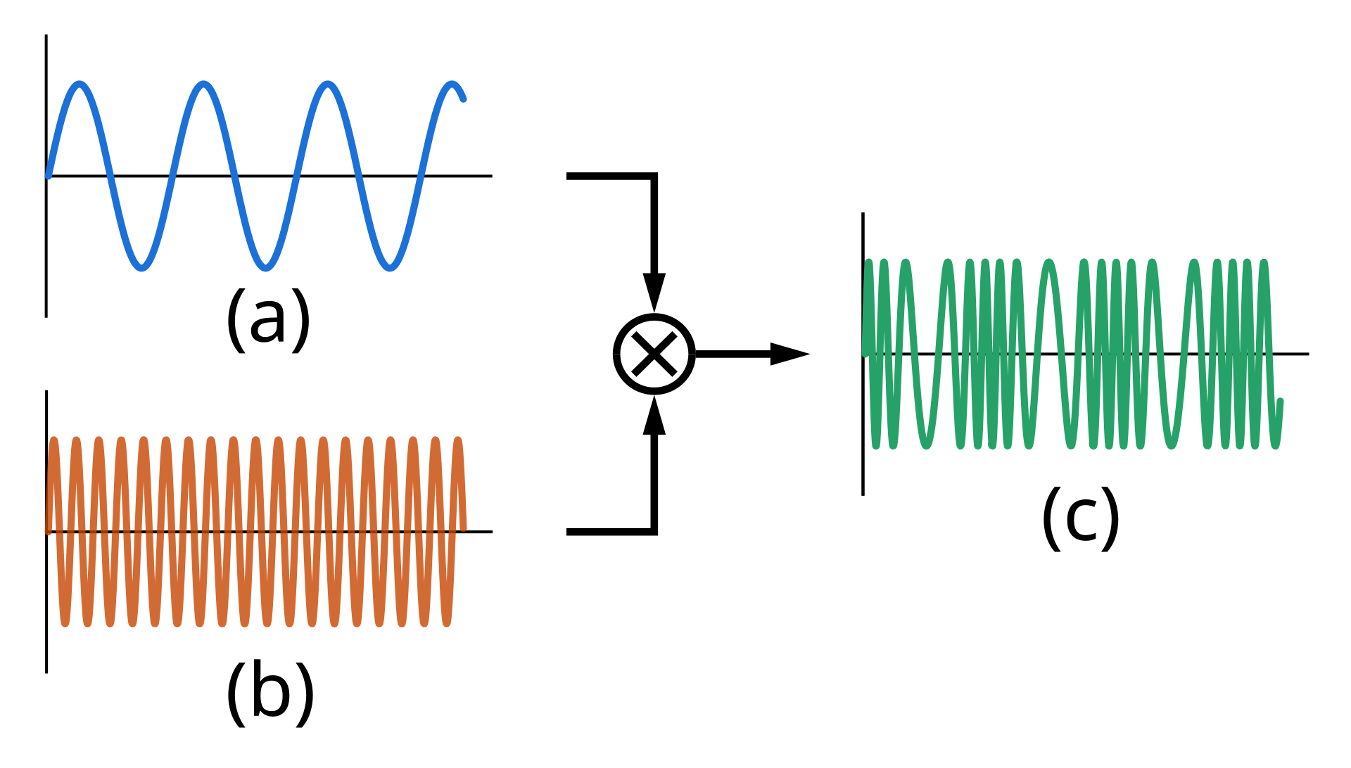
In telecommunications in general, FM means that the instantaneous frequency of the carrier changes in proportion to the instantaneous value of the modulating signal, while the amplitude of the carrier stays (mostly) the same. The best-known classic use is FM radio in the VHF band, where sound (speech, music) is turned into changes in the frequency of a radio wave.
In synthesisers, FM modulation does the same thing, but at audio frequencies: one oscillator (the modulator) changes the frequency of another oscillator (the carrier), which creates new tonal components (sidebands) and complex sounds. This gives metallic, electric, bell-like sounds, typical of FM synthesisers.
Put simply: ADSR describes how a sound breathes over time, and FM describes how we wobble the frequency to get richer and more interesting tones.
Questions
- Why is the audio signal from the Arduino not enough to drive a speaker directly, without an amplifier?
- Why can an LM386 with a higher gain sound louder, but also worse?
- Why is the bypass capacitor on pin 7 useful in audio circuits?
- Why can the same program sound better or worse just because of a different layout of the wires and ground?
- Why are rotary potentiometers a good choice for an educational instrument like this?
Diagrams and schematics